


CFD based evaluation of water pumping stations
Background
Pumping stations are facilities which include pumps and equipment for pumping fluids from one place to another. They are used for a variety of infrastructure systems, such as the supply of water, drainage and removal of sewage to processing sites. Typically, these structures are designed and assessed by physical scale modelling.
Computational modelling can provide a practical and cost-effective alternative to assess design iterations and identify critical issues in the design of pumping stations at full scale and at a significantly lower cost compared to physical modelling.
In this example, the benefits of CFD analysis are outlined in terms of evaluation of design and performance of a pumping station as well as a tool for optimisation.
Methodology
The CFD model consists of the steady state simulation of an incompressible single phase flow with water as the working fluid. A constant and uniform velocity boundary condition was imposed at the inlet of the water intake structure. The outlet was set as a surface at the end of the pump pipes. The water surface in the whole tank was modelled as a fixed interface which is free from shear.
Flow rotation in the pump pipes can cause wear and has a direct impact on the maintenance costs of the pump. This can usually be avoided or minimized by the placement flow splitters close to the pump intake. Pre-swirl rotation is a measure of the intensity of flow rotation at the pump pipes and is characterised by the swirl angle. The swirl angle is calculated as a function of the average rotation velocity of the flow and the the average axial velocity at the pump intake.
The ANSI Pump intake design standard [ANSI/HI 9.8-1998, American National Standard for Pump intake design, Hydraulic Institute (1998)] defines the acceptance criterion for the average swirl angle at the pump intake to be in a range between 5 and 7 degrees.
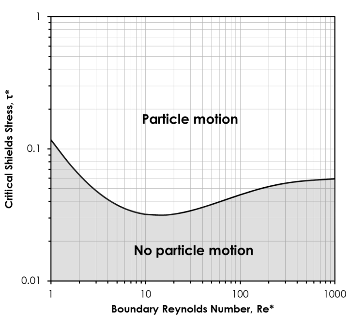
The ability of the pumping station to maintain solids’ mobility along the floor is critical to some sectors (e.g. mining or wastewater management) and must also be assessed through CFD modelling. The solids’ transport or settlement is closely related to stagnant zones formed in the pumping station.
Two non-dimensional variables, the Critical Shields Stress and the Boundary Reynolds Number are determined. This allows the direct application of the Shields criterion for different particle sizes and particle densities. The calculated value of Critical Shields Stress is compared to the limiting condition which marks the boundary between moving and static sediment along the pumping station (curve plotted in the figure on the right), based on extensive experimental work [Shields, A., Application of similarity principles and turbulence research to bed-load movement (1936)].
Example
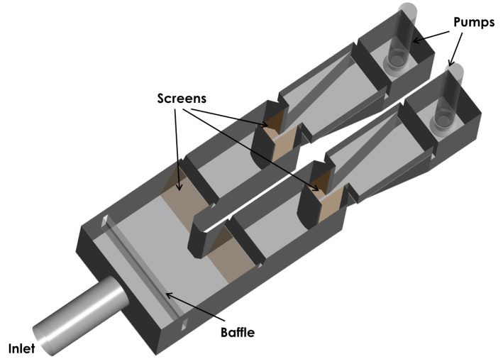
A water-intake structure for the Meizhou Wan power station in China was used as example of a pumping station where this type of analysis can be applied. The next figure shows the computational domain of the water intake structure. This structure is a two-pump, circulating, water intake with dual-flow screens. Sea cooling water enters a transition section with a horizontal baffle wall and is then diverted into two separate pump-bays. Each pump-bay is equipped with a bar screen, a dual-flow (double-entry and centre-exit) travelling screen, a curtain wall, and corner fillets.
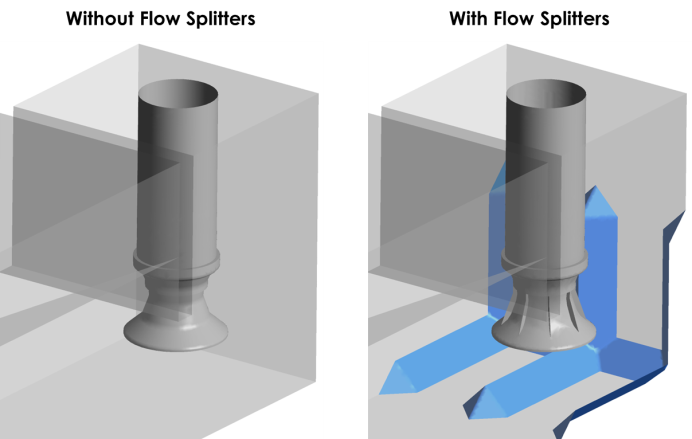
A variation of this geometry was also simulated. In this case, the geometry was optimised with floor splitters to suppress any vortices forming at the pump-throat. The next figure compares the original design with the one with flow splitters.
Hydrodynamics
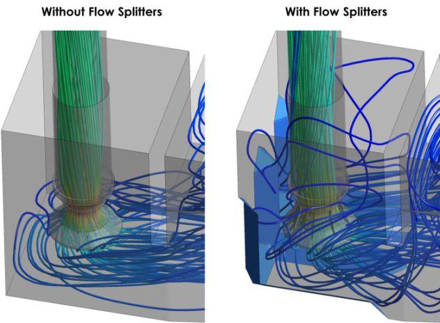
The flow distribution was computed for the entire computational domain. The results were presented in terms of flow pathline plots coloured by the velocity magnitude (see the next figure).
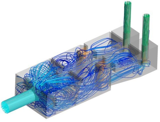
Results show several flow recirculation formations due to the expansion or contraction in different sections of the pumping station. Bending of the flow in the proximity of the pump throat is also observed and causes the flow inside the pump tube to rotate. This phenomenon is more noticeable in the structure without flow splitters (next figure, left hand side). The flow splitters applied at the inlet of the pumps significantly reduce the bending of the flow, resulting in lower pressure drops, greater pumping efficiency and reduced wear from swirl (next figure, right hand side).
Degree of pre-swirl and vortex activity
The next figures show the contours of rotational velocity and velocity vectors at the pump intake. In both cases, the flow has some level of non-uniformity and asymmetry. The effect of flow rotation is stronger for the case with no flow splitters (left hand side figure).
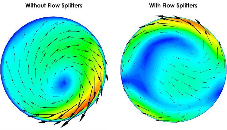
Table 1 shows the calculated results for the swirl angle.
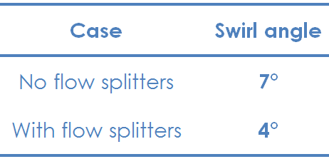
When flow splitters are not present, the pre-swirl angle is at the limit of the acceptance criterion. Pre-swirl angles calculated for the structure with flow splitters are comfortably below the limit of 5-7 degree.
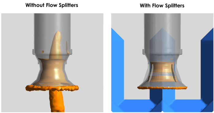
The next figures show iso-surfaces of swirling strength for both geometries. These surfaces represent zones of the domain with strong swirling where vortices are contained. For the geometry without flow splitters (left hand side figure), the formation of a subsurface vortex, below the pump-throat, is evident. The same does not occur when flow splitters are present in the pump-bay (right hand side figure). For this case, flow splitters are sufficient to suppress the formation of subsurface vortices.
It can be concluded from this analysis that the inclusion of flow splitters is beneficial for the reduction of maintenance costs by reducing the rotation of the flow in the pump pipes.
Solids settlement
Zones where the settlement of particles is likely to occur were investigated. In the calculations to determine the settling zones, standard values of size and density of sand particles were used.
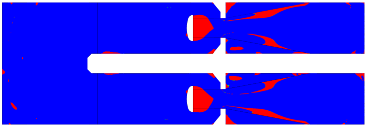
The results of the solid deposition analysis were plotted in the region corresponding to the bottom of the structure, as shown in the next figure. Zones in red indicate the zones where particle settlement is more probable. In these regions, the shear stress at the bottom of the pumping station is not sufficient to drag and suspend the particles. Simulations results show that it is highly likely for particles to settle in the dual-flow travelling screen of both lanes.
Benefits of using CFD
Computational modelling of the fluid flow in a pumping station was shown to be a valuable tool in the evaluation of the performance of the system and in the detection of problems.
The types of analyses presented here could potentially be used in the optimisation of existing structures, through the selection of more precise locations for internal modifications that can lead to an improvement in the performance of the structure.
Please see other related articles and case studies available at the PRE Technologies website. We are constantly updating our website and aim to have a wider range of case studies in the future, so do keep in touch.
Keep your curiosity in good shape.
For more information on this or any other technical white paper, please contact us.
